Filtering out the noise - Understanding IEC 61800-3 (Part 3)
Now in this final installment we will look at how the manufactures rate their levels of EMC compliance.
Basically, IEC 61800-3 defines the installation environments (as explained in the last article), general immunity requirements, general emission requirements, harmonic emissions, general test principles and documentation requirements. IEC 61800-3 then calls upon other international standards for specific limits and test methods. Although the specific EMI limits are set for each environment there is no actual requirement for each VSD to be connected with a specific configuration. Clause 4.2.1 states that the tests are to be “type” tests and “For the tests, unless otherwise specified by the manufacturer, the CDM shall be connected to a standard motor of adequate ratings with a cable and earthing rules defined by the manufacturer. In some cases, passive load conditions (resistive, or resistive and inductive) may additionally be applied (for example, for evaluation of the low-frequency emissions).”
What this means is that supplier “A” can declare that their VSD meets IEC 61800-3 (e.g. second environment) as does supplier “B”, but in reality the performance of the two products may be very different in real life; real life where you install it.
Many manufacturers will certify their drives as meeting IEC 61800-3 but with a very short cable length, a low switching frequency and a tiny motor. Often time’s just one VSD model is tested for an entire range even though the topologies of different frame sizes change, thus the EMI emissions may well be different across the range.
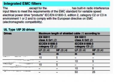
Figure 1 – Supplier “A”. Shows the maximum length of shielded cable that must be installed on various model VSD’s to permit compliance with their certification to IEC 61800-3. Additional filters can be fitted to reduce conducted emissions and increase the motor cable lengths.


Figure 1 - Supplier "A" maximum cable lengths
Figure 2 – Power Electronics SD700 shows both the output cable lengths for the entire range permitting certification to IEC 61800-3 without the need for any additional filtering, even with long cable lengths. There is no restriction on the switching frequency. Remember also that the SD700 series is certified with unscreened cables.
SD700 maximum cable lengths 
Figure 2 - SD700 maximum cable lengths
When comparing supplier “A’s” product to the SD700 range you can see that although both products claim compliance to IEC 61800-3 there is quite a margin with cable lengths and cable types. Additionally, supplier “A” has specific limitations with respect to switching frequencies. These differences need to be considered carefully when selecting between these two drive ranges.
Figure 3 shows the topology of the SD700 series 110kW – 1500kW. As can be seen there are input RFI filters to reduce high frequency conducted EMI. There are three input line reactors to limit the low frequency harmonics and there is output dV/dT filters to limit output peak voltages (a major contributor to EMI).

Figure 3 - SD700 F5 - F11 topology
So what does this mean to you the specifier or installer? It means read the fine print and ask questions of your VSD supplier!
Certification with a short cable length does not mean you will have RFI issues, it just means that should you install a cable length that is longer, you can’t be sure that the VSD does comply. Can you take the risk of EMI in the environment you are installing the VSD in? When evaluating the EMC compliance level of a given drive you need to consider a little more than just the EMC environment type and whether the VSD meets this. You need to consider the type of cable you wish to use to connect the motor; what type of cable is the VSD certified with? You need to consider the length of cable run and check with your VSD supplier. What is the switching frequency the VSD is designed to run at and will this have an effect on the cable length?
We trust these three articles on EMC and the IEC 61800-3 standard has helped clarify some of the issues surrounding the correct selection of a VSD and the requirements stipulated within the standard. Please contact Drive Dynamics should you require further detail on EMC issues.
Get in touch now to find out more.
