Power Factor Correction - Distortion or Displacement
In today’s modern electrical environment power factor correction is not quite as easy to design as in years gone by. With the advent of non-linear electrical loads, like LED lighting, UPSs, High Frequency welding machines, and the associated harmonic currents, throwing a few power correction capacitors and a power factor controller in as a solution no longer cuts the mustard. This article is aimed at demystifying the types of power factor and how “Power Factor” as a term has changed.
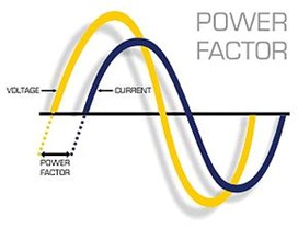
Displacement or Fundamental Power Factor (50Hz only)
Up until the early 1980’s electrical loads were very simple and normally fell into one of three categories from a power factor perspective. They were:
- Resistive – These are loads that displayed resistive characteristics only. There was no inductance or capacitance to impact on power factor. On these resistive loads the voltage and the current are in phase so no power factor correction was required. Examples of these type loads are incandescent light bulbs and heating elements.
- Inductive – These are loads that display both resistive and inductive characteristics. The inductive component of the load causes the current to lag behind the voltage, hence the term lagging power factor. These inductive loads are very common in industry and examples are AC motors, lighting ballasts, and induction furnaces.
- Capacitive – These are loads that display both resistive and capacitive characteristics. The capacitive component of the load causes the current to lead the voltage, hence the term leading power factor. These capacitive loads are uncommon but an example is an over excited synchronous motor or capacitor.
The power factor of these leading or lagging loads was always just an expression of the magnitude that the current was out of phase with the voltage, hence the term displacement power factor. By applying the same magnitude of corrective power factor (in the case of lagging power factor, a leading power factor device needs to be connected and vice versa) the original poor power factor is cancelled out and the overall power factor improves. On most sites a practical target factor is between 0.95 and 0.99 at 50Hz.
As the vast majority of power factor correction systems are to correct lagging power factor (inductive), the fix has been to connect additional leading power factor devices such as capacitors, Static Var Generators, or an over excited synchronous motor.
During this time period, significant non-linear loads such as DC drives or thyristor fired temperature controllers or motor controllers did exist but as a total percentage of the load connected to a network, were insignificant. The harmonics that they created caused little or no problem as their installation concentration was so low. So their impact on power factor was generally ignored.

A graphical representation of a lagging power factor where current lags voltage
DIStortion power factor
Have you ever been on site where you have continued to add capacitors to the power factor correction system but no matter how many more capacitors you add the power factor does not improve? There is a strong chance you are dealing with a site that has a high harmonic or non-linear loading.
Many modern installations contain electrical loads that have a high percentage of harmonic producing devices. Just think about a new office building. It probably has inverter heat pumps, LED lighting, countless computer power supplies, UPSs, maybe even VSDs for the air conditioning. The current drawn from the supply is quite different from a sinusoidal waveform. It can be full of peaks and troughs as per the example below. The distortion power factor is the distortion component associated with the harmonic voltages and currents present in the system. These harmonic currents are at multiples of 50Hz and add to the overall RMS current.

A graphical representation of a typical current waveform affected by harmonics. This is the cause of distortion power factor
No amount of capacitors will fix this type of power factor. Capacitors in a power factor system are 50Hz only devices. Distortion power factor can only be improved by removing the harmonics from the system.
True Power Factor
In today’s electrical environment we should be referring to and correcting the True Power Factor. The True Power Factor is simply the combination of both the displacement and distortion power factor. It is no longer adequate to take 30% of the site supply rating in KVAR, install a power factor controller, some contactors and capacitors and expect it to work or even last. For new installations you should undertake some modelling on the types and quantity of loads that will be connected. Strong consideration must be given to the anticipated percentage of displacement and distortion correction required. For existing sites a power quality audit should be undertaken to determine the magnitude of displacement and distortion required. Only then can a suitable solution be investigated. Power Electronics can assist with this if required.
Technology has also changed significantly. In the past displacement and distortion power factor have been corrected with individual devices - power factor correction capacitors and harmonic filters.
Now there is a device on the market that can correct both. The Advanced Static Var Generator (ASVG) from Sinexcel is capable of correcting leading or lagging power factor whilst at the same time correcting the 3rd, 5th, 7th, and 11th harmonics. With a modular and compact design the system is easy to expand for future requirements and the “two in one” minimises that expensive switchboard room real estate and minimises installation cost.
For further details please contact your local Power Electronics office or visit www.power-electronics.co.nz and ask about the ASVG.
