Power Factor Correction - Understanding the issues
Go to the internet and you can search for any number of white papers on the theories of Power Factor Correction, how to size your PF system, and engineer out issues like harmonics and resonance. But come to try and put this into practice and there are so many variables outside of the control of the system designer that it is almost impossible to ”put theory into practice”.
In this series of articles we will attempt to identify some of the design issues commonly experienced by power factor system engineers and try and unravel the mysteries of why power factor correction capacitors are so prone to failure and catching fire.
In this first article we will investigate what is and why we install power factor correction, and explain some of the pitfalls in traditional capacitor based power factor systems.
What is Power Factor Correction?
Power Factor Correction can simply be described as reducing the Reactive Power (kVAr) in an electrical system to such a point that the Apparent Power (kVA) and Real Power (kW) are very similar in magnitude. The angle between Apparent Power and Real Power is referred to as Cos ⱷ or Power Factor. Most system designers aim to have a power factor of 0.95 or greater.

Historically Power Factor Correction has been very easy to achieve. Most loads connected to the network were either resistive, no kVAr introduced so kVA and kW are equal – so no PF correction is required, or inductive, lagging kVAr is introduced which made kVA and kW unequal – so PF correction is required to bring kVA and kW back together.
Lagging kVAR can simply be cancelled out by the introduction of the same value of leading kVAr (capacitors). On a large site “banks” of capacitors are staged in and out depending how much power factor correction is required. This is type of power factor is called “displacement power factor” and is based around only the 50Hz waveform.

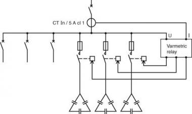
A typical site power factor correction system. Banks of capacitors controlled by a power factor controller and contactors.
The introduction of modern loads containing uncontrolled rectifiers, often called non- linear loads (eg Variable Speed Drives, Uninterruptable Power Supplies, LED lighting, Computer Power Supplies etc), has created a new problem for power factor correction designers. These devices draw harmonic currents from the supply which if significant enough can reshape both the site current and voltage waveforms. In some situations these devices actually present as leading kVAr. The type of power factor these loads create is called “distortion power factor”. No amount of capacitance will correct distortion power factor. An external device such as an Active Harmonic Filter must be used to “reshape” the voltage waveform back to sinusoidal. Loads generating distortion power factor are now becoming the norm. Just think about the electrical devices that went into that new office building down the road!

A current waveform from a non-linear load. No amount of PF capacitors can be used to fix the distortion power factor.
True power factor is the combination of both displacement and distortion power factors.
Well why do we need Power Factor Correction?
The reasons for incorporating power factor correction into an electrical system is really very simple and comes down to two keypoints:
- Cost Saving – Many electrical network and retail companies charge their customers penalties for having poor power factor. This can be done in a number of way such as:
- kVAr penalty tariffs
- Electricty usage charged in kVA rather than kW
- Maximum demand charges based on kVA rather than kW
- Fixed daily charges based on kVA rather than kW
The introduction of power factor correction can reduce these charges.
- Better utilisation of network and site capacity – Obviously reducing the amount of current being drawn through the network and site cabling allows for additional connections or loads to be connected without the need to upgrade conductors. This is a real incentive for networks as they can connect new customers without having to upgrade line capacity.
The pitfalls of using capacitors for Power Factor
As mentioned above the addition of leading kVARs to an electrical system has been a successful method used to correct lagging (displacement power factor) for many years. However with the addition of non-linear load types there has been an exponential increase in the number of power factor correction capacitors failures and fires. This has forced a complete rethink of how we can deal safely with power factor and resulted in the introduction of inverter based power factor controllers like the Sinexcel StaticVar generator or SVG. It is these topics that we will expand on in up and coming articles.
- Harmonic Currents – Harmonic currents, which are high frequency currents based on multiples of the 50Hz fundamental (for example the 5th harmonic is 250Hz and the seventh harmonic is 350Hz), see capacitors as a low impedance devices and are drawn to the capacitors. These additional currents can overload the capacitor and cause overheating. The higher the level of harmonic current the worse the overload.
StaticVar generators are inverter based so are completely immune to harmonic currents. In fact technology like that from Sinexcel can be used to mitigate both power factor and harmonic currents with one unit.
- Blocking Chokes – Many conventional capacitor based power factor units are fitted with blocking chokes. These chokes are specifically designed to stop one or two of the harmonic currents (normally the fifth and the seventh). However harmonic currents from a non-linear load appear in infinite frequencies so whilst the fifth and seventh are being blocked other harmonics can be absorbed by the capacitors. The other area often overlooked in power factor system design is the fact that the blocking choke has an output voltage of up to 10% higher than its input voltage. Thus a suitably voltage rated capacitor must be selected for reliable operation.
StaticVar generators are immune to harmonic currents so do not require blocking chokes.
- Resonance – The ultimate no-no in any system. When inductance and capacitance are equal at a certain frequency system resonance can occur. This often results in extremely high voltages circulating around the system. With linear loads it is easy to design out the possibility of resonance because you only need investigate at 50Hz. With the introduction of non-linear loads and harmonic currents system resonance can occur at several different frequencies with catastrophic results due to the high voltages introduced to the entire network.
StaticVar generators do not use capacitors to generate leading kVAr so resonance cannot occur.
- Overheating – The effect of overheating on capacitors, particularly modern self-healing capacitors, can be very dangerous. The overheating can come from either overload or poor ventilation, either way, it causes rapid deterioration of capacitor service life and results in failure. Failure can even be “runaway” and happen almost instantly.
StaticVar generators are inverter based and come with factory designed ventilation systems. If they are operated in an over-temperature environment they simply trip.
- Overvoltage –Capacitors are incredibly susceptible to damage from over voltage events. Over voltage is often just thought about as a transient that comes from the supply but the actual act of switching the capacitors in and out with contactors, as power factor requirements change, results in large voltage transients at the capacitor terminal – particularly if the capacitor is switched in when half charged.
StaticVar generators are infinitely variable within their own rating so no switching in or out of “stages” occur, removing the risk of transient overvoltage.
We hope this has whet your appetite for more knowledge on this topic so keep your eyes open for our next article explaining the indepth mechanism’s behind some of these issues.
Get in touch now to find out more.
