Harmonic Blocking Chokes - Are they a guaranteed solution for capacitor based power factor?
What does a harmonic blocking choke do?
The purpose of a blocking choke is simple. The inductance of the choke and the capacitance of the power factor correction capacitors form a simple tuned LC filter. The impedance of this is designed to allow low frequencies like 50Hz to pass easily thru the filter but to “block” high frequencies – for power factor correction systems this is normally frequencies above the fourth harmonic or 200Hz – from passing through. Because the current at these frequencies are blocked they do not enter the capacitor and cause overloading.
That sounds simple – what is the problem?
As you can see a blocking choke is a simple LC circuit. The problem is that every site has a supply impedance prior to the power factor correction system. This is the impedance of the transformers, cabling, switchgear etc. This supply impedance (Z) is made of a combination of Inductance (L), Resistance (R) and sometimes Capacitance (C). The supply impedance is connected directly to the power factor correction system (blocking chokes and capacitors) so there is electrical interaction between the two. Unless you know the exact supply impedance, and engineered this into your calculations, you may have changed the tuning point of the filter. Installation of a standard off the shelf blocking choke is not a perfect solution. It is essential the design of the blocking chokes must take system impedance into consideration. It is also important to note that any change in system impedance, for example adding a new supply transformer to site or adding further electrical infrastructure, can change supply impedance and effect existing blocking choke performance.
So what happens if the harmonic blocking chokes are not working correctly?
There are two major risks when blocking chokes do not perform as designed:
- Harmonic currents pass directly through the blocking choke and are consumed in the capacitor. The power factor capacitor is acting like a sink. These additional currents can overload the capacitor which can result in capacitor failure or fire. The total current being consumed by a capacitor can be measured by using a true RMS clamp meter and compared to the stated capacitor full load current.
- Resonance can occur at any of the harmonic frequencies resulting in high voltage and high currents circulating in the system. This can damage equipment on the entire electrical distribution system or cause the current flowing to the capacitors to increase resulting in capacitor failure and the risk of fire. This phenomenon can be easily identified by looking at the Current Total Harmonic Distortion (THDi) with a power quality meter. When resonance is occurring at the harmonic frequencies, the current being consumed by the power factor system will be greater with the power factor turned on, than when turned off. You must evaluate every capacitor step to determine possible resonant conditions for every harmonic present on the system
Tongue in cheek – harmonic resonance is said to be a self-correcting problem. Most times capacitors will fail, fuses will open, or the source transformer will fail. Any of the previous will lead to the removal of that component from the system.

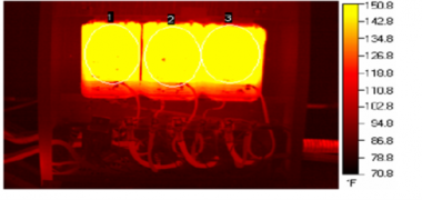
A harmonic blocking choke completely overloaded with harmonic currents

The blue trace shows an example of a plant with the power factor correction capacitors turned off (on the left) and then the power factor correction capacitors turned on (to the right). Note the correction of power factor from 0.70 at lowest, to 0.95 at best.

The red trace shows the THDi at the exact time scale of the above chart. Note the massive increase in THDi when the power factor correction is turned on. This is as a result of resonance on the 5th and 7th harmonic in this case.
So what do we do?
Our onsite power quality assessments have shown that this a more regular occurrence than you might think. In reality it is very difficult to engineer a traditional capacitor based power factor system correctly as there are too many site variables, which often don’t stay constant through plant expansions and changes, and highlights another reason to consider inverter based power factor equipment like the Sinexcel StaticVar Generator (SVG) which is harmonic immune.
Our expert team are able to conduct an onsite assessment of your existing plant power factor. Just touch base with your local Power Electronics sales engineer to discuss.