The principles of managing DV/DT in AC variable frequency drives
A typical output stage of an AC variable frequency drive consists of six transistor switches (usually IGBTs) which are turned on and off at a rate varying between 1 – 20kHz. The evolution of the insulated-gate bipolar transistor (IGBT) has meant that the latest generation devices can be turned on from zero to peak voltage in just 0.1 microseconds. This rapid turn has resulted in reduced loses and improved output waveforms but has some major drawbacks such as increased levels of RFI, motor insulation failure and motor bearing failure.
dV/dT refers to the rate of change of voltage over change in time in an electrical circuit. It is a measure of how quickly the voltage changes in a given amount of time. Managing output dV/dT in AC variable frequency drives is crucial for the reliable and efficient operation of electrical motors. Mismanaged dV/dT can cause a wealth of negative repercussions such as, electromagnetic interference (EMI), and motor failure. This is because high dV/dT can create voltage spikes that exceed the design limits of the equipment and can cause damage to electronic components.
In this blog, we’ll discuss the best practice principles of managing dV/dT in AC variable frequency drives, covering:
- The dV/dT formula – what is it and why understanding it is important in motor control applications
- The negative implications of high dV/dT – the main concerns you need to be aware of
- How to manage dV/dT – what you need to consider to prevent dV/dT induced motor failure
What is the dV/dT formula?
dV/dT relates to the speed in which it takes the VSD output IGBT to fully turn on. This is expressed in the change in voltage (Delta Voltage – dV) with respect to the time it takes (Delta time – dT) and is measured in volts per microsecond (v/us).
A high dV/dT can induce high-frequency noise or interference that can affect nearby electronic devices, leading to EMI issues. This is particularly important in motor control applications, where high dV/dT can also cause overvoltage or voltage transients that can damage motor insulation and bearings. Therefore, minimising dV/dT is critical for achieving electromagnetic compatibility (EMC) and ensuring the reliable and safe operation of electrical equipment.
Figure 1 shows a high dV/dT output voltage waveform of a VSD comprising of thousands of on/off pulses each with major voltage overshoot.

Figure 1. Typical high dV/dT output voltage waveform of VSD
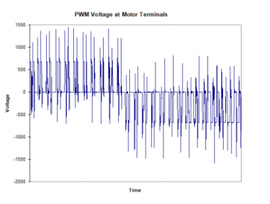
Since the time it takes for the voltage to rise from zero to peak value is so little, dV divided by such a tiny dT results in a very high dV/dT figure. On some 400V drives this can be greater than 6000v/us. In reality, when a high dV/dT pulse train is applied across a resistor/capacitor circuit (cable and motor) the resulting voltage is a large spike with a ringing tail as shown in the figure 2 wave form captured from a VSD with not dV/dT mitigation.

Figure 2. Actual output waveform of 200A VSD with no dV/dT mitigation.
What are the main problems of high dV/dT?
The main problems associated with high dV/dT are motor insulation failure, motor bearing failure (EDM), and increased levels of RFI. It has been discovered that the majority of motor failures experienced with VSD’s is due to high dV/dT.
The motor windings are subjected to these continuous fast dV/dT pulses and eventually the insulation becomes stressed and breaks down. The typical mode of failure is between turns. The first turn within the motor windings has the greatest voltage applied across it so it is often this first turn that fails. This has coined the phrase ‘first turn winding failure’.
Additionally, the drive output voltage pulses must be carried to the motor via an interconnecting cable. There is an impedance mismatch between the cable and the motor that results in a reflection of the voltage pulses once they reach the motor terminals. These reflected pulses can then be added to by the next wave front travelling out from the VSD. This addition can result in terminal voltages reaching twice the DC bus voltage (>1200V). This overvoltage effect is often referred to as ‘transmission line effect’, ‘reflected wave’ or ‘standing wave’ and is characterised by the VSD dV/dT, cable length, cable type and motor characteristics. On a VSD with no dV/dT mitigation, this reflected wave can start to have detrimental effects with only 15m of cable connected – the longer the cable run the worse the reflected wave effect and high the voltage can reach.
Such a high voltage can break down the insulation of the cable (most standard cables are rated to 1000V) but worse, damage the insulation of the motor. Smaller motors will often suffer winding to winding failures (‘punch through’) and larger motors partial discharge where unstable ozone is released that attacks the insulation compounds.

Figure 3. Peak voltage at VSD and motor terminals.
Much has been written about motor bearing failures caused by electro discharge machining (EDM). There are three recognised failure mechanisms:
- Capacitive coupling to the rotor
- Circulating currents
- Capacitive coupling from stator to ground
These failure mechanisms are produced mainly by high frequency common mode voltage output of the VSD and high dV/dT. The high switching edge produces very fast currents flowing into the motor frame, which can induce reflected currents in the rotor. This leads to circulating currents through both the bearings and frame.
Low dV/dT may also indirectly reduce capacitive discharge in certain applications by reducing motor terminal voltage overshoot (due to ‘transmission line effect’) on applications with cables exceeding 15 – 20m.
While not the sole contributor to EDM, high dV/dT has a significant impact and is its reduction alone can often be enough to eliminate EDM if the other failure mechanisms are of insufficient magnitude.
How to prevent dV/dT failure
Many of the latest generation variable speed drives (VSD) have very high rates of output dV/dT. If this is not addressed correctly the resulting peak voltage applied to the connected motor can be up to two times the level of the DC Bus Voltage. This can lead to first turn failure of the motor windings.
A common solution for this has been for suppliers to recommend the installation of an output choke between the VSD and motor. This does result in lowering of the peak voltage applied to the motor, but most suppliers will not be able to categorically confirm for you what the dV/dT rate or peak voltage level will be. Thus, the solution may not be satisfactory to comply with the motor manufacturers stated maximum levels, which can cause overvoltage or voltage transients that could damage the motor insulation and bearings, leading to premature motor failure.
How does the Power Electronics SD750 reduce over-impulses and limit dV/dT
To meet the challenges described above, the SD750 employs unique hardware that limits dV/dT at IGBT level plus incorporates output toroids which further reduce differentially coupled noise. Additionally, the low dV/dT permits the installation of unscreened motor cable with runs up to 300m being permissible. Consider applications such as submersible bore pumps (where the motor design makes them even more susceptible to the high pulse rate and voltage overshoot) and heavy industrial applications such as mining where the drive can be located well away from the motor and this extended cable length can be very beneficial.
Figure 5 shows the actual output waveform of a 200A SD750 running at full load. There are no over-impulses. The actual dV/dT (measured at the motor terminals) is less than 500V/us and the voltage overshoot is less than 1000V.

Figure 4. 200A SD750 output wave form.
Summary
The issue of dV/dT is one that cannot be overlooked when it comes to motor failures. With the increased switching speed of modern IGBTs, the risk of failures is even higher. However, a reputable drive supplier will have published information on their dV/dT levels and should be able to provide scope traces to back this up. This emphasises the importance of choosing a trusted supplier and taking the necessary steps to ensure that your motors are adequately protected from potential failures. By being aware of this issue and working with knowledgeable suppliers, you can take proactive measures to prevent motor failures and ensure the continued success of your businesses.
We're here to help. Let us show you how the SD750 can mitigate the risks of high dV/dT.